This is Part V of our Thread Inspection 101 Series.
In Part I, we discussed the basics of thread measurement and dove into what thread gages are. In Part II, we discussed the basics of thread form. In Part III, we discussed the intricacies of the Imperial thread designation system. While in Part IV, we discussed the intricacies of the Metric thread designation system.
If you have been following along with our Thread Inspection 101 Series, you now have a solid grasp on theory of thread design and can work your way through the specifications of a thread using the two thread designation systems used around the world, Imperial and Metric.
With this solid understanding of the basic fundamentals, it is time to dive into the meat and potatoes of this series, actual thread inspection.
As discussed way back in Part II, where we discussed the basics of thread form, we saw the extreme geometric complexity that goes into the design of even the simplest thread. Suddenly, some appreciation goes into the manufacturing of that “simple” nut and bolt.
Thread Inspection Error
With this extremely complex geometry, it stands to reason that the true measurement of a thread form is complex as well. The biggest issue when inspecting threads is the sheer number of elements (flanks, diameters, etc.) that come into play in the design. Each one of those elements is designed within a specified tolerance. Each element machined will have a small variance from its nominal size. Now multiply that variance by each of the elements across the entire length of the thread and you can suddenly end up with a fairly large error. This error is known as accumulative error.
The net result of this accumulative error is a deviation of the actual size of a thread from its designed size. This actual size is known as the functional size of the gage. The functional size is very important, as this is the size that will actually determine the acceptability of a thread into or around its mating component.
There are many different sources of error, but some common sources of error are:
Eccentricity
Eccentricity error occurs when the pitch diameter of a thread is not directly concentric to the axis of the thread.

Flank Angle
The flank angle of the thread is also a common source of error in the manufacturing process. Most commonly, this angle is designed to be 60°. If this angle is machined to be slightly more or slightly less than this specification, the functional size of the thread is affected.

Pitch Diameter
The most common error will come from discrepancies in the machined size of the pitch diameter for the thread. This is the most critical dimension when it comes to compatibility of two mating thread components. As discussed in Post III and Post IV, the class of fit allows for the variance in this dimension.

Roundness
Roundness error is caused by a thread that is not perfectly round. There are many different types of roundness error that can be present in the manufacturing of a thread. These errors can take the shape of many different geometric forms, from ovals to the erratic form shown below. Regardless of the shape of the error, the largest maximum and minimum dimensions (shown with the dashed lines below) represent the functional external and internal sizes, respectively.
Now that we fully understand where the common sources of error in thread manufacturing come from, we can finally get into the geometrical theory behind thread inspection.
Thread Inspection
As alluded to multiple times throughout this series, with the complicated geometry of a thread, the inspection of a thread to return a measured size is necessarily complicated as well.
When inspecting a thread, the most important dimension is its pitch diameter. This is done by placing a wire onto external threads or a ball on internal threads. The wire or ball is placed between adjacent flanks of a thread at a point that rests on the flanks at the pitch diameter.
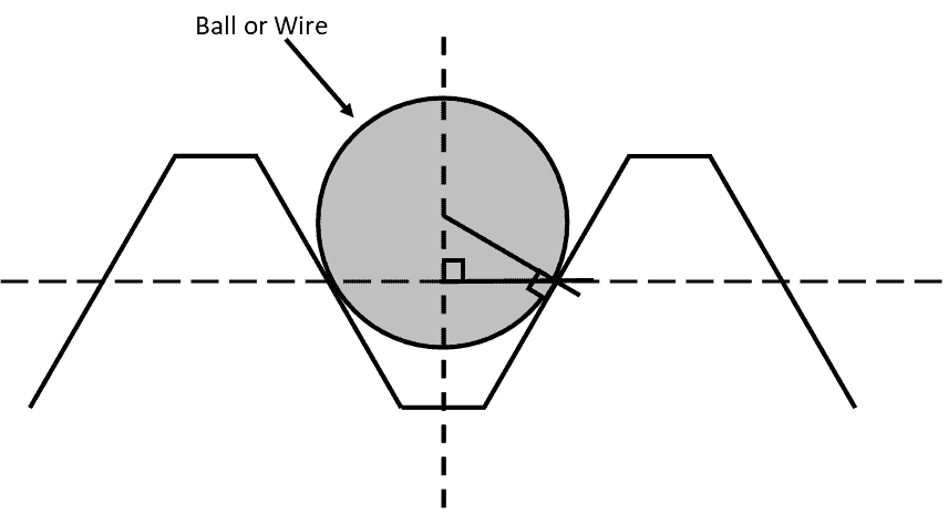
By measuring in this fashion, it is unfortunately not possible to take the errors mentioned above other than the pitch diameter into consideration. As a result, this measurement is not considered a functional inspection. In other words, this measurement won’t provide real world results of much value. See how complicated this is starting to get?
Now, as you can see by the above drawing, the geometry required to be calculated just to inspect a simple thread and provide a direct measurement is immense. It would very quickly become prohibitive to complete this inspection on every threaded component that leaves your facility. In fact, this calculation is not even in the scope of this post. This would take us down a rabbit hole that I am afraid would be too difficult to get out of. If you did care to learn more about the geometry behind this calculation, an excellent resource is available at Thread Check’s website.
The good news is, as alluded to wayyyy back in Post I of this series, there is a much easier way to complete functional checks on threaded components. That way is through the use of Go/No-Go thread gages.
Thread Gaging Inspection Basics
All thread gages are classified as an attribute gage, meaning they do not provide feedback on what the exact size of the dimension is. Thread gages accomplish this in what is called a Go/No-Go measurement. There are two arrangements:thread plugs for checking external threads and thread rings for checking internal threads.
Let’s look at a typical thread plug.
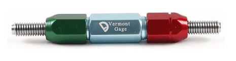
To inspect an internal thread, both ends of the thread plug are inserted into the threaded component. The Go end of the plug is supposed to thread in; the No-Go end is not. If this test checks out, the part can pass inspection. However, if the Go end does not go in, it can be deduced that the threaded component was machined too small. Subsequently, if the No-Go end does thread into the part, the threaded component was machined too large.
It is because of this incredibly speedy check that thread plugs and thread rings are some of the most common gages in the entire manufacturing industry. They can be found at nearly every machining center where threaded components are being produced.
We will dive into these thread plugs and thread rings in detail in upcoming posts. Stay tuned!
In Part VI of our Thread Inspection 101 series, we will explore the ins and outs of thread plugs and their usage.
Interested in having your thread gages calibrated? Check out our Thread Ring Calibration Services or our Thread Plug Calibration Services today!
Interested in purchasing a thread gage? Please submit a request today.