
Steve has been around the calibration industry his whole life. His father, Mark Toll, founded Fox Valley Metrology in 1996, when Steve was only 6 years old. Steven went on to graduate from Milwaukee School of Engineering, one of the most challenging and accolated technical universities in the country. This lifelong immersion in the industry has led him to become the Vice President of Sales for Fox Valley Metrology since 2014.
Thread Inspection 101 Part VIII - Thread Ring Adjustment
This is Part VIII of our Thread Inspection 101 Series.
In Part I, we discussed the basics of thread measurement and dove into what thread gages are. In Part II, we discussed the basics of thread form. In Part III, we discussed the intricacies of the Imperial thread designation system, while in Part IV, we discussed the intricacies of the Metric thread designation system. In Part V, we dove into the complicated world that is the theory behind thread inspection. In Part VI, we pulled it back into the practical realm and investigated the design and manufacture of thread plugs. We did a similar dive in Part VII, while investigating the ins and outs of thread rings.
Now that we have learned all about the usage of thread rings, it is time to dive into how an adjustable ring gage is actually adjusted.
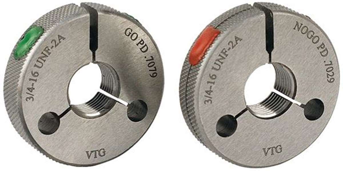
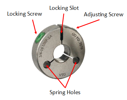
As a quick refresher, the most common type of adjustable thread ring is the American Gage Design (AGD) thread ring, shown here.

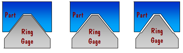
As discussed in Part VII, when any thread gage is used, ring or plug, you are rubbing metal against metal. Naturally, over time, the gage is going to wear down. What is interesting, is this wear will happen in the same spot pretty consistently over the life of the gage.
As seen here, this will create a scenario where the flank of the thread will actually have a "step" worn into it. The area that gets worn down is referred to as the "wear plane" of the gage. Unfortunately, when thread plugs get this, they cannot be adjusted and must be replaced. However, adjustable thread rings can, of course, be adjusted.
The inspection of a ring and subsequent adjustment is done with the assistance of a setting plug.
Setting Plugs
All of this works by threading the working ring onto what is called a setting (or "set") plug. The setting plug looks similar to a regular thread plug, but their usage is quite different. A setting plug is never to be used as a working plug for inspection of parts and components. It is only to be used to set and inspect thread rings.
Setting plug gages are manufactured without a plus or minus tolerance and represent the nominal size of the thread.
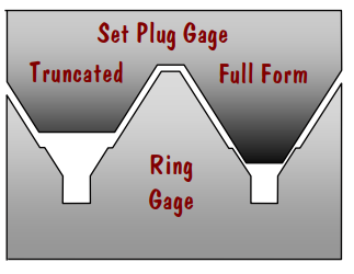
The most common type of setting plug is the truncated setting plug. The truncated setting plug contains a full form and a truncated section. The truncated portion of threads has the crest ground down flat. The thread on a truncated setting plug is continuous, as well as the pitch diameter.
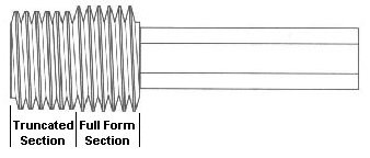
The truncated portion is designed to contact the flanks of the ring within the wear plane, almost as if it were a product being threaded into the ring. The full form section is designed to contact the flanks across the entire portion of the gage.

When a ring is checked on a setting plug, you will feel a noticeable difference in the tightness between the truncated and full form sections of the plug.
Adjusting Thread Rings
As mentioned previously, thread rings provide a unique advantage over their cousins, the thread plug, in that certain designs allow them to be adjusted. Obviously, over time, the ring is prone to being worn down. When this happens, luckily, replacement is not needed. Often times, the ring can simply be adjusted back to within tolerance.
The process for adjusting thread ring gages - as detailed by Vermont Gage, one of the foremost gage manufacturers in the world - is as follows:
- Thoroughly clean both the ring and plug gages by immersing in good cleaning solution and jet-blow dry, or preferably clean ultrasonically if possible. Then visually inspect to make sure all foreign material in the threads has been removed and no nicks or burrs are present.
- Lubricate the plug with a thin film of light viscosity oil before assembling with the ring gage.
- Turn the locking screw of the ring counter-clockwise until it is loosened, but do not remove it from the ring.
- Turn the adjusting screw clockwise to open the ring to a larger pitch diameter than the setting plug.
- Turn the ring onto the setting plug until it is completely engaged with at least one thread of the ring extending beyond the last thread on the back end of the full form section of the setting plug. (This promotes uniform wear over the entire thread length of the plug.
- Turn the adjusting screw counter-clockwise until there is a slight drag between the ring and setting plug.
- Turn the locking screw clockwise until tight, this locks the adjusting screw so that the pitch diameter of the ring remains fixed. There should now be a noticeable drag between the ring and setting plug.
- Operations No. 6 and 7 may have to be repeated more than once to get the proper adjustment.
- Unscrew the setting plug from the ring.
- Screw the setting plug into the ring approximately one and a half turns and try to move it from side to side to test the ring for a taper or bellmouth condition. NOTE: In checking for shake, use light pressure on the setting plug to avoid damaging the end threads.
- Remembering the feel at the one and a half thread engagement, screw the ring over the truncated and full form sections of the setting plug. The drag or feel should remain approximately the same, perhaps a little more drag at the full form engagement due to more flank contact.
- Remove the setting plug from the ring and repeat operation No. 11 on other side of the ring.
- The assembly of the ring and setting plug should feel the same from either side of the ring. This insures a straight pitch diameter.
When the ring gage is set to the setting plug with uniform feel over the entire length of the plug, including no end thread shake, it is correctly mated with the plug. However, it is well to remember that because of tolerances in the manufacture of both the ring and the setting plug, and that unless they are made at the same time or ordered to be mated with each other, allowances must be made in the assembly feel or fit to compensate for slight differences. For instance, a slight difference in angle and/or Lead cause more of a tightening or drag at full engagement than over partial engagements. This is not a serious condition as both the ring and setting plug may well be within specifications.
If the ring gage is set to the truncated portion of the setting plug first instead of the reverse procedure described above, and it fails to pass over the first full thread of the full form section of the plug, there is major diameter interference in the ring and it should be repaired or otherwise the ring will not engage properly.
Interested in having your thread gages calibrated? Check out our Thread Ring Calibration Services or our Thread Plug Calibration Services today!
Interested in purchasing a thread gage? Please submit a request today.
comments powered by Disqus