True-RMS Multimeters
The Definitive Guide To Using Multimeters
What is a True-RMS Multimeter?
A True-RMS (Root Mean Square) Multimeter is a device used to measure electrical values such as voltage, current, and resistance. Unlike standard multimeters, it computes the square root of the mean of the squares of values, making it precise even for non-linear loads - most commonly Alternating Current (AC)
A True-RMS multimeter uses the Root Mean Square (RMS) method of calculating a value. RMS differs from average readings because it provides an accurate representation of the effective value of alternating current (AC).
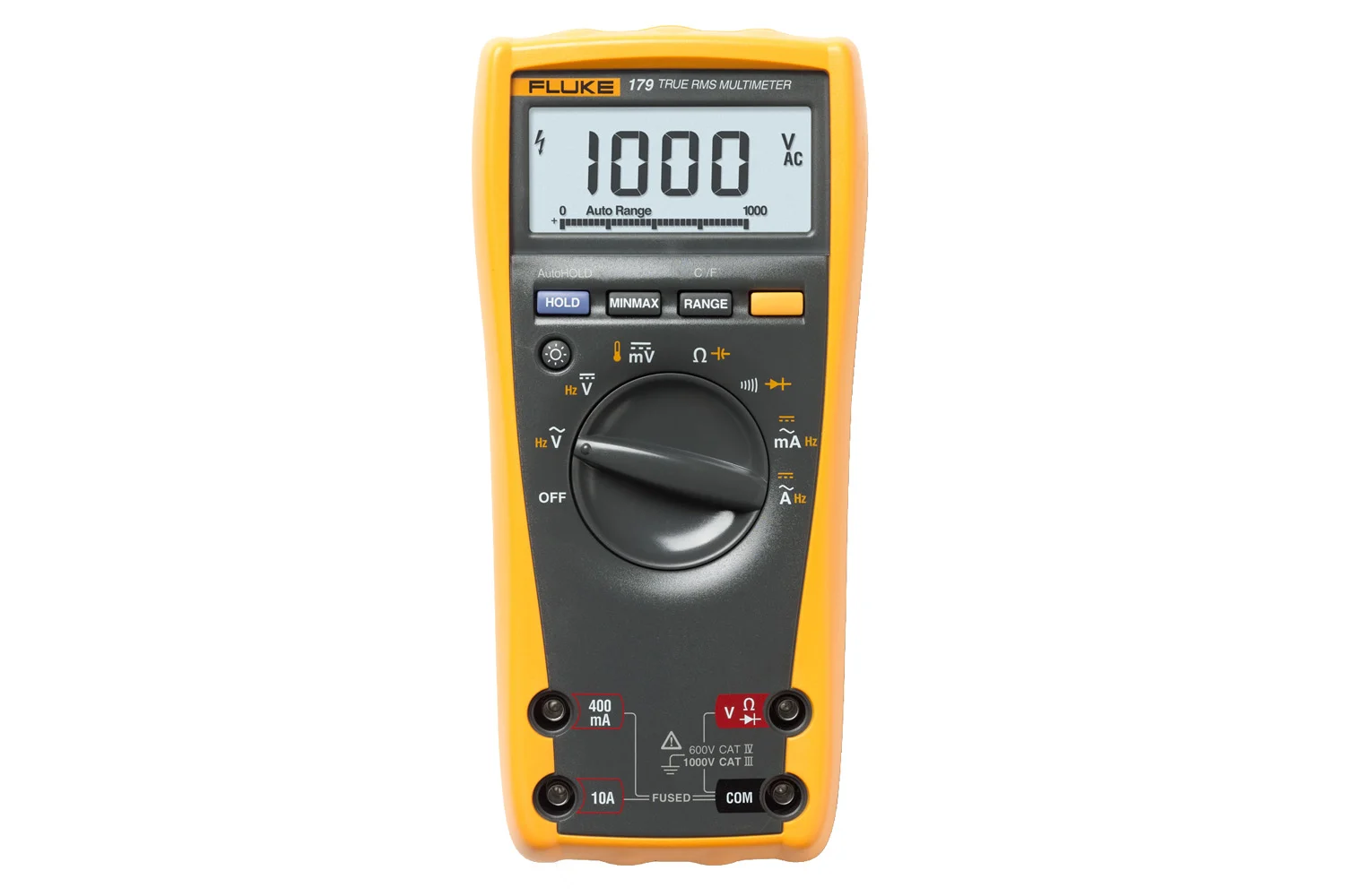
Fluke 179 True-RMS Multimeter (Image Source: Fluke Corporation)
In simpler terms, while average reading multimeters may give inaccurate readings for complex waveforms, the True-RMS will always provide the accurate electrical magnitude.
It is one of the few electrical measuring devices that can do so, outside of expensive oscilloscopes. As a result, it has become one of the most common multimeter types out there today.
the Definitive Guide to Using Multimeters
This is the 8th article in our series, The Definitive Guide to Using Multimeters.
This article delves into an indispensable breed of multimeters - True-RMS multimeters and the advantages they can offer you in your measurements - specifically when measuring complex waveforms.
In This Article
If you missed the start of the series: What Is a Multimeter: The Definitive Guide to Multimeters, check it out now! You will be able to work your way back to this article quite quickly.
The Definitive Guide to Multimeters
- What is a Multimeter?
- Why Are Multimeters Important?
- What Do Multimeters Measure?
- What is the History of the Multimeter?
- What are the Common Types of Multimeters?
- What are Common Multimeter Options?
- What are Some Multimeter Specifications?
- What are Common Uses of Multimeters?
- How Do I Choose the Best Multimeter For The Job?
- How Do I Use a Multimeter?
- How Do I Properly Maintain a Multimeter?
- How Do I Calibrate a Multimeter?
- What is the Future of Multimeters?
- Multimeter FAQs
Why Is a True-RMS Multimeter Important?
A true-RMS meter is the only multimeter that can accurately measure both sinusoidal and non-sinusoidal AC waveforms. Without this unit, you would either not get accurate measurements or require a much more expensive piece of equipment, such as an oscilloscope.
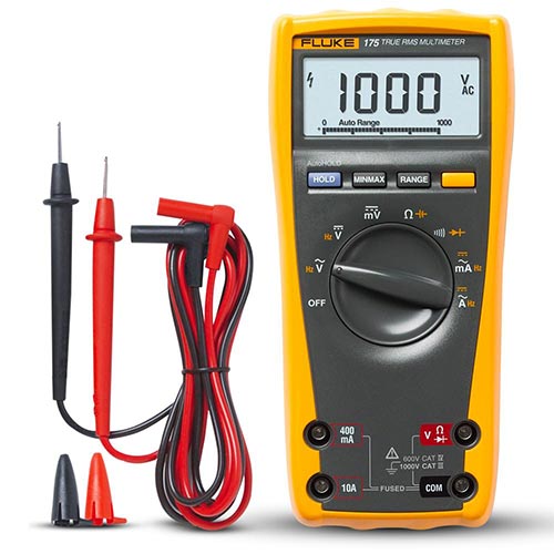
Fluke 175 True-RMS Digital Multimeter (Image Source: Fluke Corporation)
Simply put, without the option to utilize the Root Mean Square (RMS) calculation, it is nearly impossible to calculate average readings on Alternating Current (AC) signals.
What Waveforms Can a True-RMS Multimeter Measure?
Sinusoidal (Sine) Waves
A sinusoidal wave, often referred to simply as a sine wave, is a mathematical curve that describes a smooth, periodic oscillation. It is named after the sine function from trigonometry and is one of the most fundamental and ubiquitous waveforms in mathematics and the physical sciences.
Sinusoidal waves play a critical role in both the theoretical and practical realms of electrical and electronic engineering. They provide a fundamental basis for understanding and analyzing varying electrical signals.
Sinusoidal (Sine) Wave Applications
Whether it's in the form of AC power or as a carrier wave in communication systems, sine waves are integral to the functioning of numerous electrical systems and devices.
Some common examples where you can find sinusoidal waves in electrical engineering are:
-
AC Power: The electricity that powers homes and businesses in alternating current (AC) form is sinusoidal. This is why if you were to view the waveform of your home's electrical signal on an oscilloscope, it would appear as a sine wave.
-
Signal Processing: Many electronic devices process signals that can be broken down into sinusoids using techniques like Fourier analysis. By understanding how to manipulate sinusoidal components, engineers can design filters, amplifiers, and other key elements of electronic systems.
-
Communication: Sinusoidal waves are foundational in communications engineering. Radio, TV, and cellular signals often utilize modulated sine waves to transmit information.
-
Oscillators: Many electronic devices require a steady, periodic signal as a reference or clock. These are often generated using circuits designed to produce sinusoidal outputs.
-
Testing and Analysis: Sine waves are commonly used in testing electronic devices because their pure, singular frequency makes it easier to analyze a device's response.
Non-Sinusoidal Waves
Non-Sinusoidal waves are waveforms that cannot be represented as a single frequency sine wave. Instead, they are composed of multiple sine waves (of varying frequencies and amplitudes) superimposed on each other. Non-sinusoidal waves have shapes distinct from the smooth, regular oscillations of sinusoidal waves.
Non-Sinusoidal Waveforms
Here are some of the primary types of non-sinusoidal waveforms:
-
Square Wave: A waveform that alternates between two levels, typically high and low, with a 50% duty cycle. It spends equal time in the high and low states, making sharp transitions between them. Square waves are commonly used in digital circuits and clocks.
-
Triangle Wave: As the name suggests, this waveform has a triangular shape. It continuously moves between a high and low value in a linear fashion. The rise and fall times are symmetrical, making the waveform periodic and consistent.
-
Sawtooth Wave (or Ramp Wave): This waveform rises linearly over time and then sharply drops back to its initial value (or vice versa, depending on orientation). It resembles the teeth of a saw, hence the name.
-
Pulse Wave: This is similar to a square wave, but the time it spends in the high state versus the low state is not necessarily equal. The ratio of the 'on' time to the total period is called the duty cycle. Pulse waves are used extensively in Pulse Width Modulation (PWM) applications.
-
Rectangular Wave: A form of pulse wave where the 'on' and 'off' times can vary, making it appear as a series of rectangles rather than perfect squares.
-
Impulse (or Dirac Delta) Function: Though more of a mathematical concept than a tangible waveform, the impulse function represents a single, infinitely sharp peak. It's utilized in signal processing, particularly in convolution operations.
-
Step Function (or Heaviside Function): Represents a sudden jump from one value to another, typically from zero to one, and then remains constant. It's frequently used in control systems and circuit analysis to simulate a sudden change in input.
-
Modulated Waves: These are waves where attributes (like amplitude, frequency, or phase) of a sinusoidal carrier wave are altered or modulated according to a non-sinusoidal waveform. Examples include Amplitude Modulated (AM) and Frequency Modulated (FM) signals in radio broadcasting.
Non-Sinusoidal Wave Applications
While sinusoidal waves form the foundation of our understanding of waveforms and signals, non-sinusoidal waves hold immense importance in various facets of electronics and communication systems. These complex waveforms offer unique challenges and benefits, making them indispensable in modern electrical engineering. Some common applications are:
-
Pulse Waves in Digital Electronics: In digital circuits, signals often take the form of square or rectangular pulses, representing binary states (0s and 1s). These are inherently non-sinusoidal.
-
Pulse Width Modulation (PWM): This is a technique used in electronic circuits to control power by adjusting the width of a square pulse. It's utilized in applications like motor speed control and LED brightness modulation.
-
Signal Processing: When working with non-sinusoidal waves, it's crucial to understand their harmonic content. Filtering out certain harmonics or understanding the waveform's spectral content can be key in many applications.
-
Overshoot and Ringing: Non-sinusoidal waves, especially sharp pulses, can cause overshoots and ringing in circuits due to their sudden transitions. This is a significant consideration in high-frequency circuit design.
-
Fourier Analysis: Any non-sinusoidal periodic waveform can be represented as a sum of sinusoidal functions (sines and cosines) using Fourier analysis. This analysis helps in understanding the frequency components of the waveform, which is crucial in many areas, including communications and audio processing.
-
Communication: Some advanced communication methods use complex waveforms or pulses, inherently non-sinusoidal, to transmit information more efficiently.
-
Switching Power Supplies: These supplies operate by rapidly switching on and off, generating non-sinusoidal waveforms. Proper filtering is required to ensure that the output is as close to a DC level or desired waveform as possible.
Benefits of Using a True-RMS Multimeter
The evolving nature of electronic devices and the increasing prevalence of non-linear loads underscore the importance of True-RMS Multimeters. By providing consistent accuracy across a range of waveforms and applications, these devices have become an essential instrument in the toolkit of anyone working with electrical and electronic systems.
The most obvious benefits of using a True-RMS Multimeter are:
Accurate readings for non-linear loads:
Understanding Non-linear Loads
Unlike linear loads which have a constant relationship between their voltage and current, non-linear loads cause current harmonics and don't have a proportional voltage to current relationship. Devices like computers, LED lighting systems, and many modern electronic appliances fall under this category.
Challenge with Average Reading Multimeters
Traditional average-responding multimeters might provide misleading readings when measuring non-linear loads. This is because they are calibrated to measure sine wave signals, assuming that the waveform being measured is purely sinusoidal.
Precision with True-RMS
In contrast, a True-RMS Multimeter accurately computes the effective value of any waveform, regardless of its shape. This makes it indispensable when working with the complex waveforms produced by non-linear loads. As a result, professionals can trust their readings, ensuring safety and efficiency in various applications.
Versatility in various electrical scenarios:
Diverse Waveforms
In real-world scenarios, electrical signals aren't always perfect sine waves. They can be distorted due to various factors like electronic interference, harmonic generation, or the nature of the connected devices.
Adaptability of True-RMS
A True-RMS Multimeter is designed to adapt to these changes in waveform shapes. It doesn't just measure sine waves but can accurately measure the root mean square of any repetitive waveform, be it sinusoidal or non-sinusoidal.
Range of Applications
Whether you're troubleshooting a home appliance, inspecting industrial machinery, or evaluating a complex electronic circuit, a True-RMS Multimeter delivers consistent accuracy. This reliability ensures that it's a go-to tool for electricians, technicians, and electronics enthusiasts alike, allowing them to carry out measurements with confidence across various settings.
How Are True-RMS Measurements Calculated?
For a True-RMS multimeter to compute the RMS value of a waveform, it essentially follows these mathematical steps:
- Square the Waveform Value
- Compute the Mean (or Average) of the Squared Values
- Take the Square Root of the Mean Squared Value
The term RMS stands for "Root Mean Square." It's a mathematical approach to represent the effective value or magnitude of a varying quantity. The RMS calculation essentially provides a measure of the effective power of a waveform.
In practical terms, a True-RMS multimeter often employs an analog or digital method to perform this computation. Analog methods might involve the use of thermal methods (like a heated coil) which respond to the heating effect of the current. The more common digital methods will sample the waveform many times per period, square these values, average them, and then take the square root to obtain the RMS value.
For periodic waveforms, this computation is done over one period, but for non-periodic signals, a specific time window is used.
Here are the steps on how a True-RMS multimeter computes the RMS value of a waveform:
1. Square the Waveform Value
For each point in time on the waveform, the value of the waveform (be it voltage or current) is squared. This ensures all values are positive, and it emphasizes the peaks of the waveform.
- Squared Value = Value x Value
2. Compute the Mean (or Average) of the Squared Values
This is done over one full period of the waveform. This average provides a "mean" squared value.
- Mean of Squared Values = (1/T) x ∫ Squared Value(t)dt
- Where:
- is the time period of one full cycle of the waveform.
- The integral represents the area under the squared waveform curve over one period.
- Where:
3. Take the square root of the mean squared value
The square root returns the measurement to the original units (like volts or amperes) and provides the RMS value.
- RMS Value = Mean of Squared Values ^ (1/2)
What's Next: The Definitive Guide to Multimeters
We have now fully reviewed all the common construction types of multimeters and the game-changing world of True-RMS multimeters.
In the next section, we will dive into the remaining common options on multimeters, most notably around data output and test lead options. Lets get started and head to Section 9: Multimeter Accessories, Features & Options.
ISO/IEC 17025 Accredited Multimeter Calibration
Fox Valley Metrology proudly offers accredited precision measuring instrument calibration services of Multimeters. We calibrate all types of Multimeters at our offices throughout the country, meaning we are sure to have local Multimeter calibration services near you.
- ✓ ISO 17025 accredited calibration vendor
- ✓ Broadest calibration scope in the industry
- ✓ 3-5 day turnaround time for laboratory calibrations
- ✓ Pickup and delivery service options available
- ✓ Onsite calibrating service options